Spanning Tree Protocol – STP
- The Spanning Tree Protocol is a link management protocol that is designed to support redundant links while at the same time preventing switching loops in the network. It is quite useful and should be enabled on the switch interfaces.
- STP has high convergence time; it can take up to one minute to converge and provide redundancy. A newer development is implemented to the STP protocol, called the Rapid Spanning Tree Protocol (RSTP). The latter retains all the tasks of STP whilst minimizing convergence time significantly.

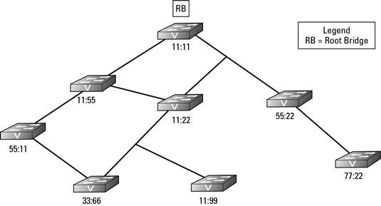
- The root bridge needs to be elected. Two fields combined together identify the root bridge: MAC address and Priority value. Without manual configuration all switches have the same priority therefore it is up to the MAC address to decide upon the root bridge. The switch with the lowest MAC address value is elected as the root bridge. In the diagram above Switch C is the elected root bridge.
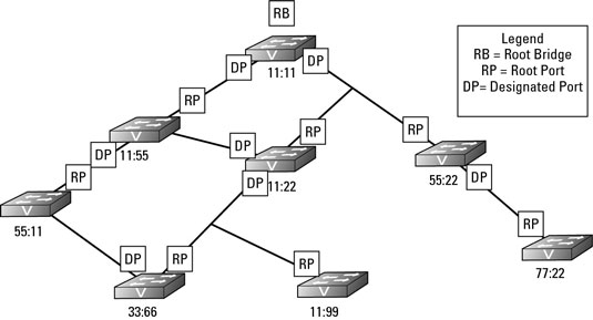
- Once the root bridge is elected, each switch needs to identify a single root port – the port closest to the route bridge. This port will always be in the forwarding state. By default all ports of the route bridge are in the forwarding state. Moreover, one port per segment (called designated port) is allowed to be in the forwarding state.
- In our example we have 2 ports on switch A and two ports on switch B that belong to the same segment. Therefore, two of them need to be blocked to avoid loops. Since switch B has higher MAC address value (hence lower priority), its designated ports need to be blocked.
- The result of all this is that only one path from one switch to any other switch exists.
Identifying Root Ports

The BPDU, which every switch sends, contains information about the switch and its Bridge ID that uniquely identifies the switch on the network. The Bridge ID is made of two components: a configurable Bridge Priority value (which is 32,768 by default) and the switch MAC address.
If none of the switches on your network has had its Bridge Priority values adjusted, then the switch with the lowest MAC address will be the Root Bridge; but if the Bridge Priority values on your network have been modified, the Root Bridge will be the switch with the lowest Bridge Priority value. The Root Bridge shown in the preceding figure is switch 11:11.
After the Root Bridge is identified, all other switches determine the quickest path from themselves to the Root Bridge. Some switches have more than one path to the Root Bridge due to a network loop. In the preceding figure, switch 11:22 has two paths, one that is two hops away from the Root Bridge and one that is one hop away.
If the speed of the networking technology is the same for all network segments, the path with the fewest number of hops is designated as the Root Port.
The switch will identify which of its interfaces is the Root Port. Each network technology has a rated speed, so based on the technology of each network segment between the switch and the Root Bridge, the switch is able to calculate the cost of each available path.
Root Bridge Election ;
– Switch the lowest Bridge ID in network becomes Root Bridge. Bridge ID contains ;
- Bridge Priority (0, 4096, 8192..) —- 4 bit
- System ID extension (vlan id) —- 12 bit
- Mac address
Blocking Loops

You still have one outstanding problem to resolve. There are still loops on this network that threaten to bring the current network down; however, by working through how all the Root Ports and Designated Ports are assigned, you have actually completed the work to resolve the loop issue on the network.
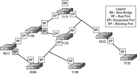
In the figure immediately preceding this section, only two ports are used to connect to neighboring switches that are neither Root Ports nor Designated Ports. Because these ports do not have either role assigned to them, they are part of a loop on the network. If you review the figure, you should be able to identify the loops on the network. To resolve the loop issue, STP puts these ports without a role into Blocking state, which means these are Blocking Ports.
Blocking Ports are ports that do not allow traffic to be sent or received through the port; it is blocking the traffic. Essentially, you could say that the Blocking Ports have been disabled, but they are not disabled. Since the ports are not disabled, the switch on the other end of the link still sees the link as active, but frames that are sent over that link (excluding BPDU frames) are dropped (blocked).
The following figure shows you the completed STP diagram, including the Blocking Ports.


